X5 Wire Feeder HD300
This section describes the structure of the X5 Wire Feeder HD300.

|
Model-specific variations may occur. |
X5 Wire Feeder HD300:
|
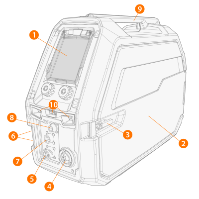
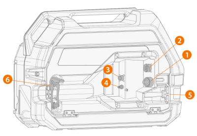
1.
|
Control panel (and control panel display cover) |
>> For more information on the X5 Wire Feeder 300 Manual control panel, refer to Control panel of X5 WF 300 Manual and HD200 Manual.
>> For more information on the X5 Wire Feeder 300 AP/APC control panel, refer to AP/APC control panel.
|
2.
|
Wire feeder cabinet door |

|
Keep the wire feeder cabinet door closed during welding to reduce the risk of injury or an electric shock. Keep the cabinet door closed also at other times to keep the inside of the wire feeder clean. |
|
3.
|
Wire feeder cabinet door latch |
|
4.
|
Euro connector for welding cable connection |
|
5.
|
Control cable connector |
|
6.
|
Coolant inlet and outlet connectors (color-coded) |
|
7.
|
Subfeeder synchronization connector |
|
8.
|
AP/APC models only: Voltage sensing cable connector |
|
|
Suspending the equipment from the handle with dedicated suspension accessories (i.e. for lifting or moving) is possible. |
|
10.
|
LED work lights with light switch in the middle |
>> Light switch: First press turns the lights on (full brightness), second press dims the lights (medium brightness), third press turns the lights off
>> Includes a built-in battery (the battery is charged when the equipment is connected to mains).
|
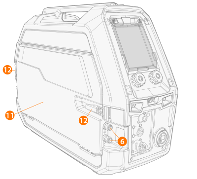
11.
|
Interconnection cable cabinet hatch |
|
12.
|
Interconnection cable cabinet hatch latches |
Inside wire feeder (wire feeder cabinet)
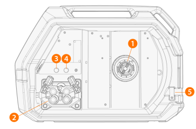
>> For more information on the wire spool, refer to Installing and changing wire (X5 WF HD300).
|
2.
|
Wire feed roll mechanism |
>> Test the shielding gas flow and flush the gas line.
>> Drive the filler wire forward (with arc off).
|
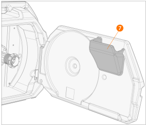
5.
|
Aperture for wire drum kit conduit (optional) |
>> For updating software/firmware.
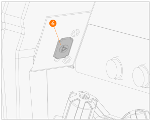
>> For temporarily storage of smaller items.
If the optional built-in rotameter for gas is used, it is also located in the wire feeder cabinet.
If the optional cabinet heater is used, its ON/OFF switch is located in the wire feeder cabinet.
Inside wire feeder (interconnection cable cabinet)
|
1.
|
Welding current cable connector |
|
2.
|
Control cable connector |
|
3.
|
Voltage sensing cable connector |
|
4.
|
Shielding gas hose connector |
|
5.
|
Coolant hose mounting slot |
|
6.
|
Interconnection cable strain relief (adjustable) |
For installing and connecting the cables, refer to X5 interconnection cable and Installing cables (X5 WF 200, X5 WF 300, X5 WF HD300).
|
|
With X5 Wire Feeder HD300, the wire feeder cabinet door opens on the side. This should be noted when considering installing a double wire feeder setup on a double rotating plate. |