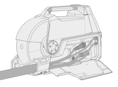
Installing cables (X5 WF 200, X5 WF 300, X5 WF HD300)
Connect the interconnection cable first to the wire feeder and then to the power source. For the connector descriptions and their locations, refer to X5 Wire Feeder 200, X5 Wire Feeder 300 or X5 Wire Feeder HD300 (depending on your wire feeder model).
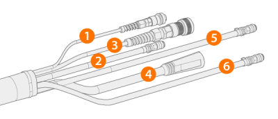
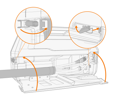
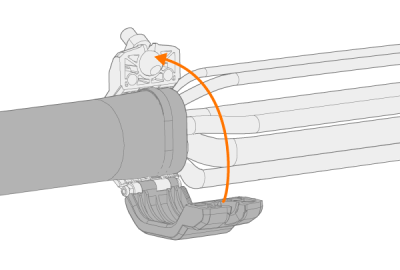
Connecting interconnection cable to wire feeder
|
1.
|
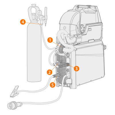
Open the cable cabinet hatch to reveal the connectors. |
|
2.
|
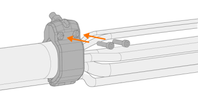
Connect the welding current cable (4) to the wire feeder. Push the cable as far as it goes and turn the connector clockwise to tighten the cable to its place. |

|
Tighten the welding current cable as much as you can by hand. If the welding current cable connection is loose, it may overheat. |
|
3.
|
Push the shielding gas hose (2) to the shielding gas hose connector so that it locks down. |
|
4.
|
Connect the control cable (3) to the connector. Rotate the collar clockwise to lock it in place. |
|
5.
|
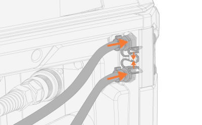
If you have the optional cooling unit, place the cooling liquid hose connectors (5, 6) into the slot and through the aperture. |
>> Compress the spring fastener to get the hose connectors in place. Once released, ensure that the spring fastener locks in place into the hose connector grooves.
|
6.
|
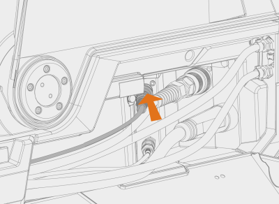
If you have the voltage sensing cable (1) in use, connect it to the voltage sensing cable connector inside the cabinet. |

|
The separate voltage sensing cable is supported by Pulse+ power sources only. |
|
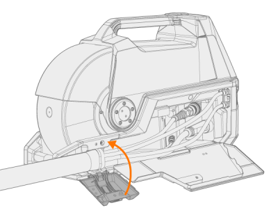
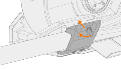
7.
|
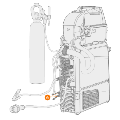
Secure cable strain relief. |
>> X5 Wire Feeder 200: Place the cable to the slot on the wire feeder and secure it in place by closing the hatch and locking the latches.
>> X5 Wire Feeder 300: Place the cable's strain relief block to the slot on the wire feeder and secure it in place by closing and locking the strain relief latch.
|
|
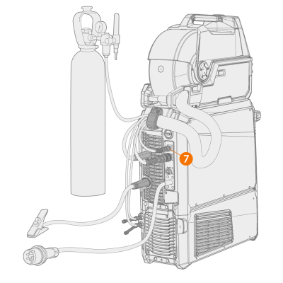
Check the expanding locking knob tightness and tighten if necessary:
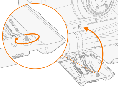 |
Tip: Additional X5 Wire Feeder 300 strain relief fixing (M6x16 screw), optional:
 |
|
8.
|
X5 Wire Feeder 300: Close and lock the cable cabinet door. |
|
|
When connecting the cables to the wire feeder, route the cables neatly so that the cable cabinet door closes properly. |

|
The interconnection cable heats up during welding. The wire feeder's cable cabinet door must be kept closed when welding, and the cables must be handled with caution if the cabinet door is opened right after welding. |
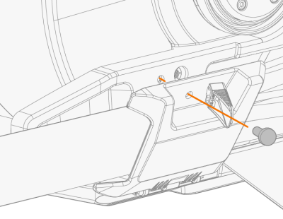
Connecting interconnection cable and earth return cable to power source
|
1.
|
Attach the cable's strain relief (1) to the rear fixing plate. |
|
2.
|
Connect the welding current cable to the plus (+) connector (2) on the power source. |
|
3.
|
Connect the earth return cable to the minus (-) connector (5) on the power source. |
|
4.
|
Connect the control cable (3) to the power source. |
|
5.
|
Connect the shielding gas hose (4) to the gas bottle. |
|
6.
|
If you have the optional cooling unit, connect the cooling liquid hoses (6). The hoses are color-coded. |
|
7.
|
Pulse+ power source only: If you have the voltage sensing cable in use, connect it to the connector (7) on the rear of the power source. |
|
|
Most MIG/MAG applications and filler wires run the wire feed unit's welding current cable connected to the positive terminal of the
power source. The polarity can be selected by connecting the welding current cable and earth return cable accordingly to
either the positive or negative connectors on the power source. |
|
|
For TIG welding, the polarity (+/-) must be switched. The polarity can be selected by connecting the welding current cable and earth return cable accordingly to
either the positive or negative connectors on the power source. |
|
|
For double wire feeder installation, use the interconnection cable designed for two wire feeders. |
|
|
Ensure that you have connected and tightened all the cables properly. |
Strain relief replacement
Removing and replacing the strain relief at the power source end of the interconnection cable:
|
1.
|
|
|
2.
|
|