X5 Wire Feeder 200
This section describes the structure of the X5 Wire Feeder 200 Manual.

|
Keep the wire feeder covers closed during welding to reduce the risk of injury or an electric shock. Keep the covers closed also at other times to keep the inside of the wire feeder clean. |
|
|
The handle is intended for short distance manual carrying. Suspending the equipment temporarily from the handle with slings (e.g. for moving) is allowed. |
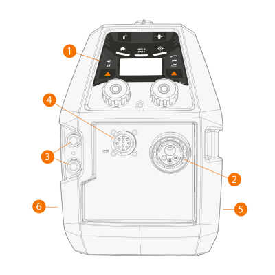
>> For more information on the X5 Wire Feeder 200 Manual control panel, refer to Control panel of X5 WF 200 Manual.
|
2.
|
Euro connector for welding cable connection |
|
3.
|
Coolant inlet and outlet connectors (color-coded) |
|
4.
|
Control cable connector |
|
5.
|
Wire feed cabinet side |
|
6.
|
Interconnection cable cabinet side |
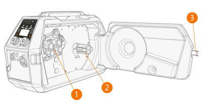
Inside wire feeder (wire feed cabinet)
|
1.
|
Wire feed roll mechanism |
>> For more information on the wire spools, refer to Wire spool and hub (200).
|
3.
|
Wire feeder cabinet door latch |
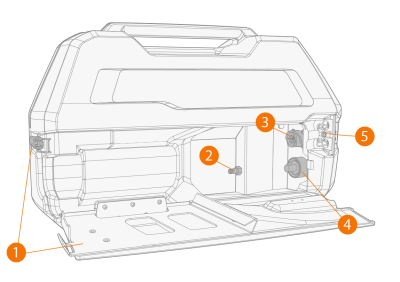
Inside wire feeder (interconnection cable cabinet)
|
1.
|
Interconnection cable cabinet hatch and locking latch |
>> The rear section of the hatch acts also as a strain relief for the cable
|
2.
|
Shielding gas hose connector |
|
3.
|
Control cable connector |
|
4.
|
Welding current cable connector |
|
5.
|
Coolant hose mounting slot |
For installing and connecting the cables, refer to X5 interconnection cable and Installing cables (X5 WF 200, X5 WF 300, X5 WF HD300).
Wire feeder fixing accessories
X5 Wire Feeder 200 can be equipped with a steel pipe frame for additional protection and installation options. When the steel pipe frame is used, X5 Wire Feeder 200 can also be installed on top of the X5 power sources using the same optional fixing accessory sets than with the X5 Wire Feeder 300.