Installing and changing wire (X5 WF HD300)
This section describes how to install the wire and spool on X5 Wire Feeder HD300.

|
Install the welding gun to the wire feeder before installing the wire spool. |
|
|
When changing the wire spool, remove the remaining filler wire from the welding gun and wire feed mechanism before removing the wire spool. |
To remove the wire spool:
|
1.
|
Open the wire feed cabinet door. |
|
2.
|
Loosen and remove the spool fastener and remove the wire spool. |
To install a new wire spool:
|
1.
|
Open the wire feed cabinet door. |
|
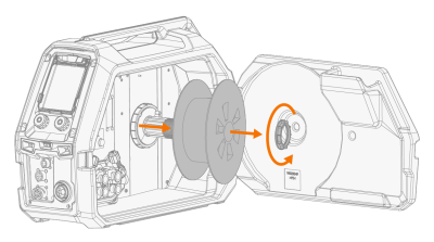
2.
|
Insert the wire spool onto the spool hub. Secure the wire spool in place by inserting and tightening the spool fastener. |

|
Ensure that the wire spool is facing the right direction, the filler wire running from the bottom of the spool to the feed rolls. |

|
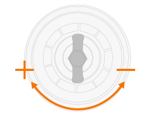
3.
|
If needed, adjust the spool brake by turning the spool brake tightening knob in the center of the spool hub. |
To install the filler wire:
|
1.
|
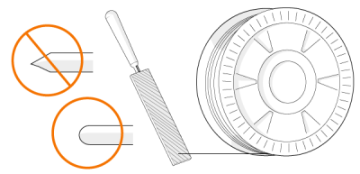
Release the filler wire end from the spool and cut off any deformed section so that the end is straight. |
|
|
Ensure that the filler wire does not spill from the spool when it is released. |
|
2.
|
File the tip of the filler wire smooth. |

|
Sharp edges on the filler wire tip may damage the wire liner. |
|
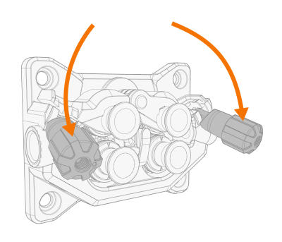
3.
|
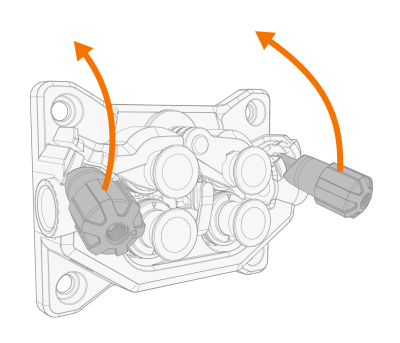
Release the pressure arms to move the feed rolls apart. |
|
4.
|
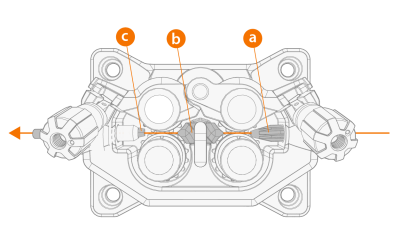
Guide the filler wire through the inlet tube (a) and middle wire guide tube (b) and into the outlet tube (c), which feeds the filler wire to the welding gun. |
|
5.
|
Push the filler wire by hand into the gun so that the wire reaches the wire liner (approx. 20 cm). |
|
6.
|
Close the pressure arms so that the filler wire is locked between the feed rolls. Ensure that the filler wire sits in the feed roll grooves. |
|
7.
|
Adjust the pressure of the feed rolls with the pressure adjustment wheels. The pressure is the same for both feed roll pairs. |
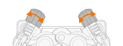
The graduated scales on the pressure handle indicate the pressure applied to the feed rolls. Adjust the pressure of the feed rolls according to the table below.
| Fe/Ss solid |
V-groove

|
0.8−1.0 |
1.5−2.0 |
| ≥ 1.2 |
2.0−2.5 |
| Metal and flux cored (MC/FC) |
V-groove, knurled
 |
≥ 1.2 |
1.0−2.0 |
| Self-shielded (gasless) |
V-groove, knurled
|
≥ 1.6 |
2.0−3.0 |
| Aluminum |
U-groove
 |
1.0 |
0.5−1.0 |
| 1.2 |
1.0−1.5 |
| 1.4 |
1.5−2.0 |
| ≥ 1.6 |
2.0−2.5 |
|
|
Excessive pressure flattens the filler wire and may damage coated or cored filler wires. Excessive pressure also unnecessarily wears the feed rolls and increases gearbox load. |
|
8.
|
Press the wire inch button to drive the filler wire into the welding gun. Stop when the wire reaches the welding gun's contact tip. |

|
Watch out for the wire when it reaches the contact tip and exits the gun. |
|
9.
|
Before welding, ensure that the welding parameters and settings on the control panel conform to your welding setup. |
>> Refer to Using X5 AP/APC control panel for more information.