Connecting cables to power source and RCM
This section describes the cable connections in the power source, RCM and the optional cooling unit. For the connector descriptions and their locations, refer to X5 Power Source 400 and 500 and Robot Connectivity Module (RCM) .
For information on connecting the protective earth cable, refer to Connecting PE (protective earth) wire (optional).
For information on connecting the fieldbus module, refer to Installing fieldbus module.
|
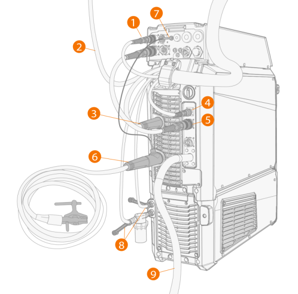
1.
|
Connect the wire feeder control cable (1) to RCM. |
|
2.
|
Connect the shielding gas hose (2) to the gas bottle. |
|
3.
|
Connect the welding current cable (3) to the positive (+) connector on the power source. |
|
4.
|
Pulse+ power source only: If you have the voltage sensing cable in use, connect it to the connector (4). |
|
5.
|
Connect the RCM control cable (5) between RCM and power source. |
|
6.
|
Connect the earth return cable (6) to the negative (-) connector in the power source. |
|
7.
|
Connect the touch sensor cable to the touch sensor negative (-) connector in RCM (7). |
|
8.
|
If you have the optional cooling unit, connect the cooling liquid hoses (8). Note that the coolant filter must be attached to the coolant inlet connector. For information on attaching the filter, refer to Installing cooling unit (optional). |
|
9.
|
Connect the mains cable (9) to the mains after the installation is complete. |