X3 Wire Feeder HD200
This section describes the structure of the X3 Wire Feeder HD200.
|
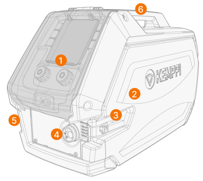
1.
|
Control panel (and hinged control panel display covers) |
>> For more information on the X3 wire feeder control panel, refer to X3 control panel.
|
2.
|
Wire feeder cabinet door |

|
Keep the wire feeder cabinet door closed during welding to reduce the risk of injury or an electric shock. Keep the cabinet door closed also at other times to keep the inside of the wire feeder clean. |
|
3.
|
Wire feeder cabinet door latch |
|
4.
|
Euro connector for welding torch cable |
|
5.
|
Coolant inlet and outlet connector holder |
|
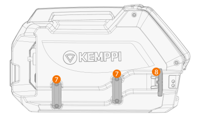
7.
|
Coolant hose duct/recess brackets |
|
8.
|
Coolant hose connector bracket and spring fastener. |
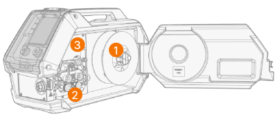
Inside wire feeder (wire feeder cabinet)
|
1.
|
Wire spool and spool hub |
>> For more information on the wire spool, refer to Installing and replacing filler wire and wire spool.
|
2.
|
Wire feed roll mechanism |
|
3.
|
Shielding gas flow regulator valve |

|
A separate model version with a built-in rotameter for gas is also available. In that case, the gas flow regulator valve is replaced with the rotameter adjustment knob and scale. |
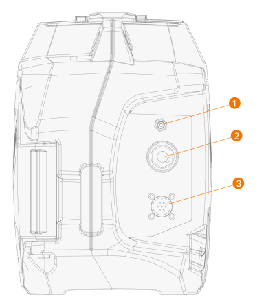
Wire feeder rear
|
1.
|
Shielding gas hose connector |
|
2.
|
Welding current cable connector |
|
3.
|
Control cable connector. |
For installing and connecting the cables, refer to X3 interconnection cables and Installing cables (X3 WF HD200).