Installing and replacing filler wire and wire spool
This section describes how to install the filler wire and spool on X3 wire feeder.

|
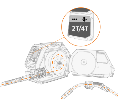
Install the MIG welding torch to the wire feeder before installing the wire spool. |
|
|
When changing the wire spool, remove the remaining filler wire from the MIG welding torch and wire feed mechanism before removing the wire spool. |
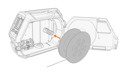
To install the wire spool:
|
1.
|
Open the wire feed cabinet door. |
|
2.
|
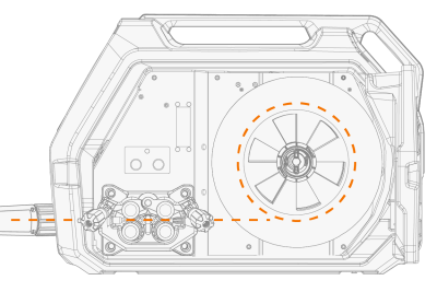
Insert the wire spool onto the spool hub and push the spool into the wire feeder until the securing mechanism locking clips lock it in place. |
|
|
Ensure that the wire spool is facing the right direction, the filler wire running from the bottom of the spool to the feed rolls. |
|
|
When installed, the pin next to the wire spool hub in the wire feeder must align and go into the hole in the spool or spool adapter. X3 HD300 wire feeder: For the wire spool adapter options, refer to Wire spools (X3 WF HD300). |
|
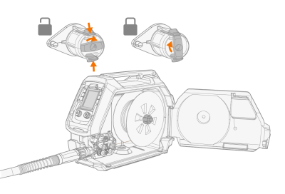
3.
|
Secure the locking clips by turning the lever in the spool hub center. |
|
4.
|
If needed, adjust the spool's brake force by turning the spool brake tightening screw in the center of the spool hub. |
>> Brake force can be adjusted by turning the adjustment screw with a flat screwdriver (X3 HD300) or with an allen key (X3 HD200) through the center hole in the locking lever.
|
|
The load applied varies depending on the size and weight of the filler wire and spool, but also
the filler wire feed speed. The heavier the wire spool and the faster the wire feed speed, the
greater the need to increase the braking load. Adjust the pressure, secure the locking clip, set
the wire feed speed and check that the braking force is enough to ensure the filler wire does
not spill from the spool on overrun. |
To remove the wire spool:
|
1.
|
Release the locking clips by turning the lever in the spool hub center. |
|
2.
|
Press the locking clips slightly towards the center. |
|
3.
|
Remove the wire spool. |
To install the filler wire:
|
1.
|
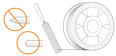
Release the filler wire end from the spool and cut off any deformed section so that the end is straight. |
|
|
Ensure that the filler wire does not spill from the spool when it is released. |
|
2.
|
File the tip of the filler wire smooth. |

|
Sharp edges on the filler wire tip may damage the wire liner. |
|
3.
|
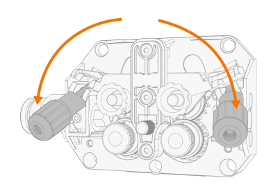
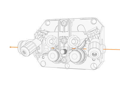
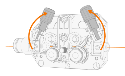
Release the pressure roll locking arms to move the feed rolls apart. |
|
4.
|
Guide the filler wire through the inlet tube and middle wire guide tube and into the outlet tube, which feeds the filler wire to the MIG welding torch. |
|
5.
|
Push the filler wire by hand towards the MIG welding torch so that the wire reaches the wire liner (approx. 20 cm). |
|
6.
|
Close the pressure roll locking arms so that the filler wire is locked between the feed rolls. Ensure that the filler wire sits in the feed roll grooves. |
|
7.
|
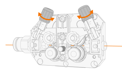
Adjust the pressure of the feed rolls with the pressure roll locking arm knobs. |
>> The graduated scales on the pressure roll locking arms indicate the pressure applied on a relative scale from 1 to 10.
|
|
Apply even pressure on both pressure handles |
|
|
Excessive pressure may cause damage to the filler wire (especially aluminum and cored/coated filler wires) and impede the feeding of the filler wire. Excessive pressure also increases the wire feed mechanism load. |
|
8.
|
Close the wire feeder cabinet. |
|
9.
|
Press the wire inch button to drive the filler wire into the MIG welding torch. Stop when the wire reaches the MIG welding torch's contact tip. |
>> In X3 wire feeder the wire inch function is activated by long-pressing the trigger logic button in the control panel.

|
Watch out for the wire when it reaches the contact tip and exits the welding torch. |
|
10.
|
Before welding, ensure that the welding parameters and settings on the control panel conform to your welding setup. |
>> Refer to X3 control panel for more information.