Installing and changing wire (X5 WF 300)
This section describes how to install the wire and spool on X5 Wire Feeder 300.

|
Install the welding gun to the wire feeder before installing the wire spool. |
|
|
When changing the wire spool, remove the remaining filler wire from the welding gun and wire feed mechanism before removing the wire spool. |
To remove the wire spool:
|
1.
|
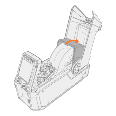
Open the wire feeder top cover. |
|
2.
|
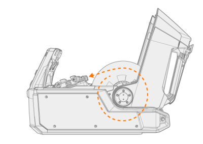
Push the wire spool locking cover to the rear. |
|
3.
|
Remove the wire spool from the wire feeder. |
|
4.
|
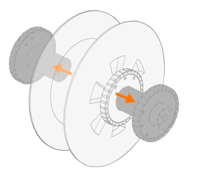
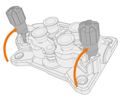
To remove the spool brake hub, release the spool brake tightening knob in the brake center and pull the brake halves apart. |
To install a new wire spool:
|
1.
|
Open the wire feeder top cover and the wire spool locking cover. |
|
2.
|
Attach the wire spool brake halves to the new wire spool by pushing them together inside the wire spool. Secure them together by turning the tightening knob in the brake center. |
|
|
Attach the spool brake hub to the wire spool so that the tightening knob is on the right, seen from the front. |
|
3.
|
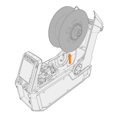
Place the wire spool into its socket. |
|
|
Ensure that the wire spool is facing the right direction, the filler wire running from the top of the spool to the feed rolls.
|
|
4.
|
Secure the wire spool in place by closing the wire spool locking cover. |

To install the filler wire:
|
1.
|
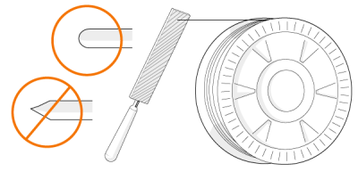
Release the filler wire end from the spool and cut off any deformed section so that the end is straight. |
|
|
Ensure that the filler wire does not spill from the spool when it is released. |
|
2.
|
File the tip of the filler wire smooth. |

|
Sharp edges on the filler wire tip may damage the wire liner. |
|
3.
|
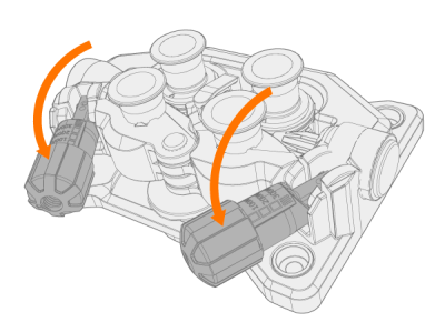
Release the pressure arms to move the feed rolls apart. |
|
4.
|
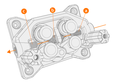
Guide the filler wire through the inlet tube (a) and middle wire guide tube (b) and into the outlet tube (c), which feeds the filler wire to the welding gun. |
|
5.
|
Push the filler wire by hand into the gun so that the wire reaches the wire liner (approx. 20 cm). |
|
6.
|
Close the pressure arms so that the filler wire is locked between the feed rolls. Ensure that the filler wire sits in the feed roll grooves. |
|
7.
|
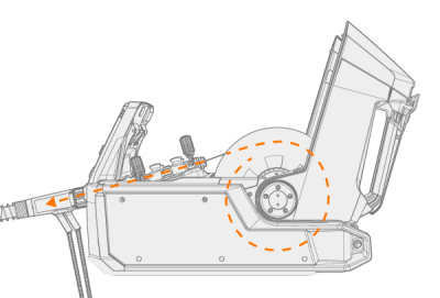
Adjust the pressure of the feed rolls with the pressure adjustment wheels. The pressure is the same for both feed roll pairs. |
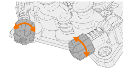
The graduated scales on the pressure handle indicate the pressure applied to the feed rolls. Adjust the pressure of the feed rolls according to the table below.
| Fe/Ss solid |
V-groove

|
0.8−1.0 |
1.5−2.0 |
| ≥ 1.2 |
2.0−2.5 |
| Metal and flux cored |
V-groove, knurled
 |
≥ 1.2 |
1.0−2.0 |
| Self-shielded (gasless) |
V-groove, knurled
|
≥ 1.6 |
2.0−3.0 |
| Aluminum |
U-groove
 |
1.0 |
0.5−1.0 |
| 1.2 |
1.0−1.5 |
| 1.4 |
1.5−2.0 |
| ≥ 1.6 |
2.0−2.5 |
|
|
Excessive pressure flattens the filler wire and may damage coated or cored filler wires. Excessive pressure also unnecessarily wears the feed rolls and increases gearbox load. |
|
8.
|
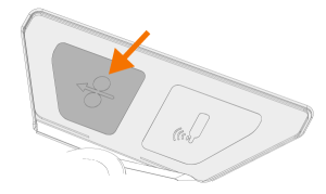
Press the wire inch button to drive the filler wire into the welding gun. Stop when the wire reaches the welding gun's contact tip. |

|
Watch out for the wire when it reaches the contact tip and exits the gun. |
|
9.
|
Before welding, ensure that the welding parameters and settings on the control panel conform to your welding setup. |
>> Refer to Using X5 Manual control panel and Using X5 AP/APC control panel for more information.
Wire spools and hubs (300)