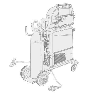
Installing gas bottle and testing gas flow

|
Handle gas bottles with care. There is a risk of injury if the gas bottle or the bottle valve is damaged! |

|
Always secure the gas bottle properly in an upright position to a special holder on the wall or on the welding equipment cart. Always keep the gas bottle valve closed when not welding. |

|
- If a transport unit with a gas bottle rack is used, install the gas bottle on the transport unit first, then make the connections. - Install the welding torch to the wire feeder before installing and testing the gas bottle. - Do not use the whole contents of the bottle. - Always use an approved and tested regulator and flow meter. |
Contact your local Kemppi dealer for choosing the gas and the equipment.
| 1. | Without gas bottle cart: Place the gas bottle in a suitable, secure location. |
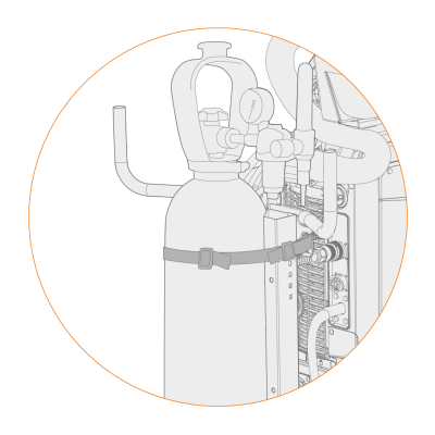
| 2. | With gas bottle cart: Move the gas bottle on the transport unit's gas bottle rack and secure it in place with the straps and fixing points provided. |
| 3. | If not already, connect the welding torch to the wire feeder. |
| 4. | Connect the gas hose to the wire feeder. |
|
|
In a standard setup, the gas hose is included in the interconnection cable bundle (for more information, refer to Installing cables (X5 WF 200, X5 WF 300, X5 WF HD300) or Installing cables (X5 WF HD200)). |
| 5. | Open the gas bottle valve. |
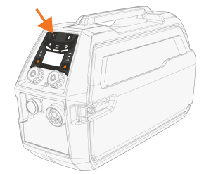
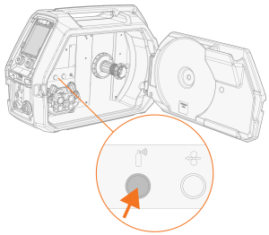
| 6. | Press the Gas test button in the wire feed cabinet to flush the previous shielding gas and to run the new gas into the system. |
>> With X5 Wire Feeder 200 Manual the Gas test button is located on the control panel:
>> With X5 Wire Feeder 300 the Gas test button is located in the wire feed cabinet:
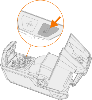
>> With X5 Wire Feeder HD200 the Gas test button is located in the wire feed cabinet:
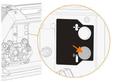
>> With X5 Wire Feeder HD300 the Gas test button is located in the wire feed cabinet:
| 7. | Press the Gas test button again to adjust the gas flow. Use either the built-in rotameter or an external flow meter and regulator for measuring and adjustment. |
|
|
Use the Gas test button also to test that the gases flow through the system properly. |
Recommended gas flow rates (for general guidance only):
| TIG* | MIG** | |
|---|---|---|
| Argon | 5...15 l/min | 10...25 l/min |
| Helium | 15...30 l/min | - |
| Argon + 18-25% CO2 | - | 10...25 l/min |
| CO2 | - | 10...25 l/min |
* Depending on the gas nozzle size.
** Depending on the gas nozzle size and welding current.
Adjusting gas guard (optional)
The sensitivity level of the optional (with X5 Wire Feeder HD300 only) gas guard can be adjusted as follows.
| 1. | Open the interconnection cable cabinet. |
| 2. | Turn the gas guard adjustment screw with a flathead screwdriver to adjust the sensitivity in the desired direction (+/-). |
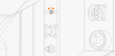
| 3. | Test that the gas guard works correctly with the new setting. |
The gas guard can be turned on and off in the control panel settings: Manual control panel: Settings and AP/APC control panel: Device settings.