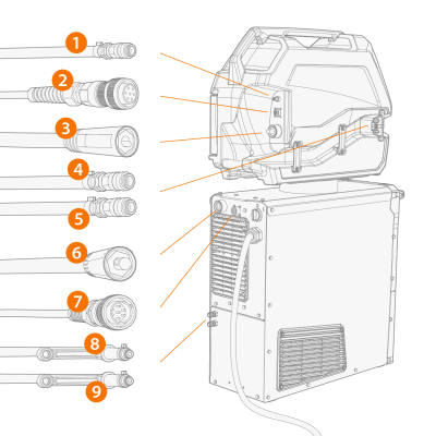
Installing cables (X3 WF HD300)
Connect the interconnection cables first to the wire feeder and then to the power source. For the connector descriptions, refer to X3 Wire Feeder HD300.
Tools needed:

|
Route the cables as neatly as possible. |
|
1.
|
Connect the welding current cable (3) to the wire feeder. Push the cable as far as it goes and turn the connector clockwise to tighten the cable to its place. |

|
Tighten the welding current cable as much as you can by hand. If the welding current cable connection is loose, it may overheat. |
|
2.
|
Push the shielding gas hose (1) to the shielding gas hose connector so that it locks down. |
|
3.
|
Connect the control cable (2) to the connector. Rotate the collar clockwise to lock it in place. |
|
4.
|
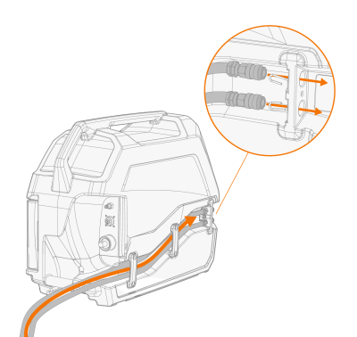
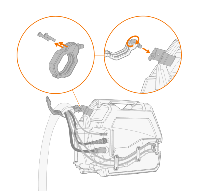
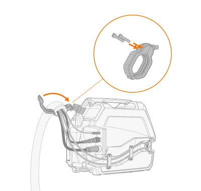
If you have the optional cooling unit, place the cooling liquid hoses (4, 5) into the recess on the wire feeder side and the connectors through the apertures. |
|
5.
|
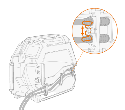
Compress the spring fastener to secure the hose connectors in place. Once released, ensure that the spring fastener locks in place into the hose connector grooves. |
|
6.
|
Secure the cable fasteners. |
|
7.
|
Connect the welding current cable (6) to the plus (+) connector on the power source. |
|
8.
|
Connect the control cable (7) to the power source. |
|
9.
|
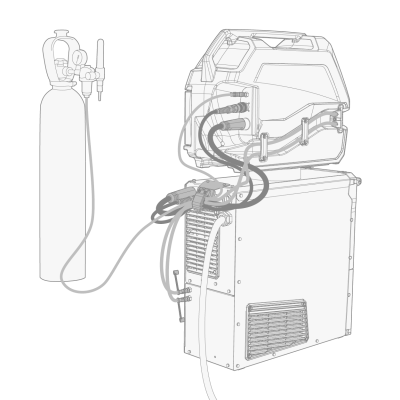
Connect the shielding gas hose to the gas bottle. |
|
10.
|
If you have the optional cooling unit, connect the cooling liquid hoses (8, 9) to the cooling unit. The hoses are color-coded. |
|
11.
|
As applicable, secure the cables with the included cable clamp(s) depending on your equipment installation. The cable clamps helps to guide the cables and act as a strain relief. |
|
|
The 1.5 meter interconnection cables come with one cable clamp attached in the power source end of the cable.
The 5 meter and longer interconnection cables have two cable clamps attached, one in the power source end of the cable and one in the wire feeder end of the cable. |
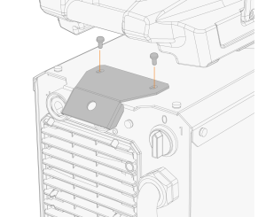
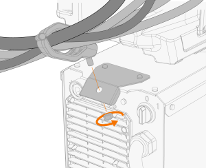
>> If the wire feeder is installed on top of the power source, the attached cable clamp can be secured to the optional support bracket on the power source (with the nut provided):
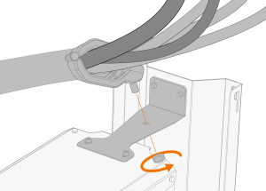
>> With the optional cart, secure the attached cable clamp to the cart support bracket (with the nut provided):
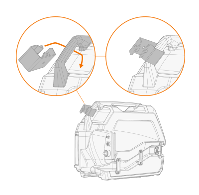
>> 5 meter and longer cables: To secure the wire feeder end of the interconnection cable, place the additional support bracket around the wire feeder's rear handle and secure the cable clamp to it (with the nut provided).
For connecting the earth return cable and MIG welding torch to the system, refer to Connecting welding torch and earth return cable.
|
|
Most MIG/MAG applications and filler wires run the wire feed unit's welding current cable connected to the positive terminal of the
power source. The polarity can be selected by connecting the welding current cable and earth return cable accordingly to
either the positive or negative connector on the power source. For this purpose, an additional cable extension for the interconnection cable's welding current cable is available as an optional extra. |
|
|
Ensure that you have connected and tightened all the cables properly. |

|
The interconnection cable heats up during welding. The cables must be handled with caution right after welding. |

