Connecting backup power supply (optional)
The backup power supply is used to ensure that the fieldbus connection stays active even when the main current of the welding power source is cut off. When the backup power supply is used, all control functions are disabled.
Backup power supply technical requirements
| Feature | Value |
|---|---|
| Supply voltage | 24 V +- 10 % |
| Minimum continuous current | 2 A |
| Output isolation | SELV (Safety Extra Low Voltage) |

|
As the backup power supply is not isolated from the RCM’s normal system potential, use a separate power supply to avoid connecting different circuit potentials together. |
|
|
Turn off the power source before connecting the backup power supply. |
For instructions on removing and attaching the RCM top cover, refer to Removing and attaching RCM top cover.
| 1. | Pass the cable for the backup power supply through a cable inlet on RCM. (For information on cable inlets, refer to Routing cables into RCM.) |
| 2. | Connect the wire to the backup power supply terminal (*) on the RCM main board. |
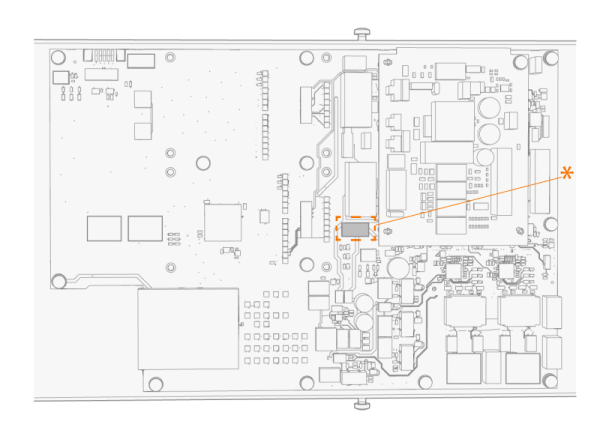
|
Terminal pins: 1. Backup power input + 2. Backup power input + 3. Backup power GND 4. Backup power GND |