Control Pad views: Welding
In the Welding view, you can:
| • | See an overview of the settings of the selected welding program |
| • | Adjust the main parameters (welding power and fine tuning) |
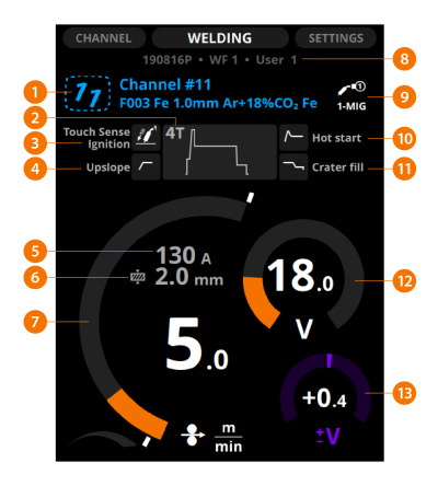
Depending on the selected welding process, function and program, some or all of the following information is shown:
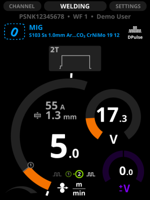
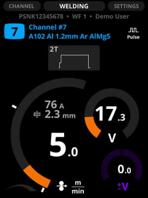
| 1. | Memory channel, its number and the welding program |
>> The first row shows the memory channel's name.
>> The second row shows the welding program's name, which consists of the filler wire material and diameter and the shielding gas.
>> If you have modified the welding settings, the channel number tilts to the right. To save changes, press and hold the Channel button until the number returns to its normal position.
| 2. | Operation mode of the welding gun (trigger logic) |
>> 2T, 4T or WP Switch. For more information, see Trigger logic functions.
| 3. | Touch sense ignition |
>> Option for smooth ignition with less spatter.
| 4. | Upslope |
>> The selected start and stop logics.
| 5. | Estimated welding current |
| 6. | Estimated plate material thickness |
| 7. | Wire feed speed |
| 8. | Serial number of the power source, wire feeder's number (1 or 2) and user name |
| 9. | Welding process |
| 10. | Hot start |
>> The selected start and stop logics.
| 11. | Crater fill |
>> The selected start and stop logics.
| 12. | Voltage |
| 13. | Voltage/Fine tuning |
Adjust the welding power with the left control knob.
Fine tune the secondary welding parameter with the right control knob. The adjustable secondary parameter varies according to the welding process and function.
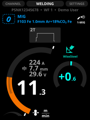
The welding power graph shows with grey raster pattern the area, where the selected values result in globular transfer.
Figure: Raster pattern in the wire feed arc.
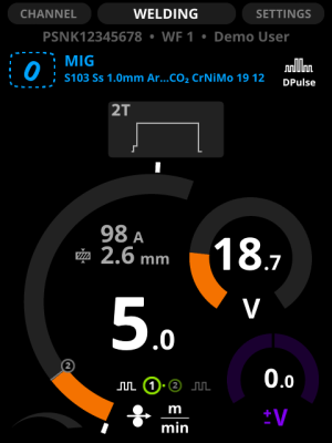
In DPulse, WP Switch and DProcess, you can adjust two value sets: the first level and the second power level. Press the left green button to toggle between them. Adjust the values with the control knobs. The other power level is shown with gray line on the wire feed speed diagram.
Figure: Toggling DPulse (1) / Toggling DPulse (2).
You can specify the minimum and maximum values of the wire feed speed. They are displayed as white stoppers beside the wire feed speed diagram.
Figure: The minimum and maximum stoppers.
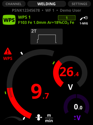
The value range of the welding power and voltage graphs specified by the Welding Procedure Specification (WPS) are displayed with a green arc between the stoppers. The stoppers are by default at the top and bottom of the specified WPS area, but you can adjust them to your preferences: to narrow the area or to weld outside the specified area.
Figure: The minimum and maximum stoppers for WPS.
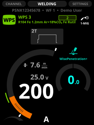
If you adjust the wire feed speed or voltage to a level outside the WPS range, the parameter graph turns red and a warning symbol appears on the display.

|
If you have installed WeldEye, it saves the data as unsuitable use, even if the welding job requires such values. |
Figure: Values outside the range specified by WPS.