X8 Wire Feeder
This section describes the structure of X8 Wire Feeder.
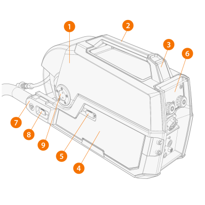
Main parts

|
Keep the wire feeder top cover closed during welding to reduce the risk of injury or an electric shock. Keep the top cover closed also at other times to keep the wire feeder insides clean. |
|
|
The handle is only intended for short distance manual carrying. Use Wire Feeder Hanger for Boom for lifting or hanging the wire feeder. |
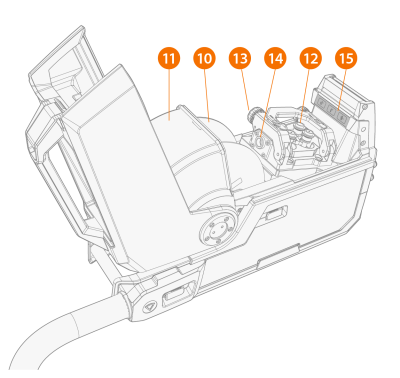
The warning sticker inside the wire feeder:

|
11.
|
Wire spool locking cover |
|
15.
|
Inside control buttons |
Control panel
The control panel on the front of the wire feeder enables easy control of the wire feeder's basic features. Although Control Pad is the main control of the welding system, you can also use the wire feeder control panel or the welding gun remote control.
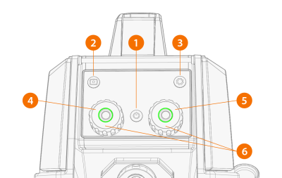
The wire feeder control panel parts are:
>> Press and hold for 2 seconds to lock or release the display and buttons.
>> The button lights up blue, when the view is activated.
>> The button lights up orange, when the view is activated.
For more information on the use and features of the control panel, see Wire feeder views.
Control buttons on the inside
The wire feeder has control buttons inside the wire cabinet.
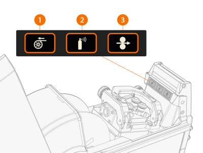
>> Drive the filler wire backward with arc off.
>> Test the shielding gas flow, or flush out the remainder of the previous gas.
>> Drive the filler wire forward with arc off.
Interconnection cable connectors
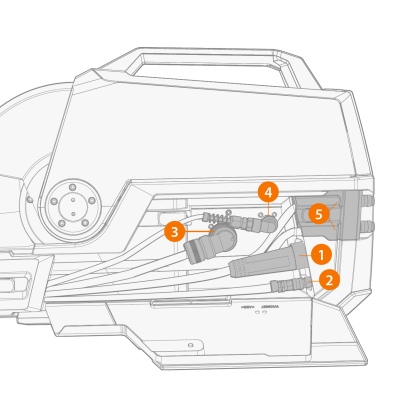
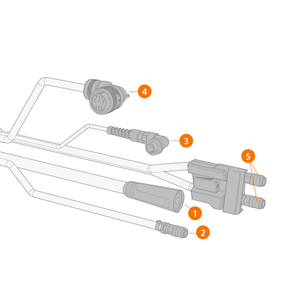
>> Supplies current from the power source to the wire feeder.
>> Supplies shielding gas to the welding gun.
>> Supplies the welding parameters measured during welding.
>> Supplies data and operating voltage to the wire feeder.
|
5.
|
Coolant outlet and inlet |
>> Circulates coolant to and from the welding gun.
For information on the installation of the cables, see Cables installation.
External component connectors
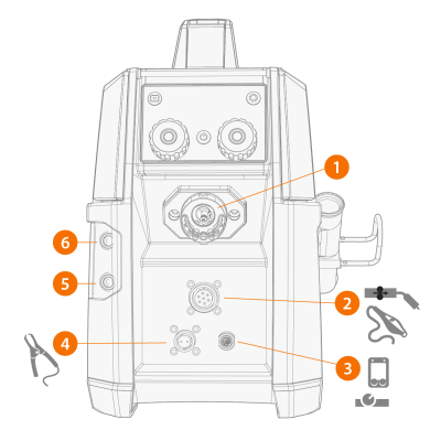
>> Connects to the welding gun.

|
The wire feeder is supplied with Kemppi Gun Adapter. |
>> Provides control to optional SuperSnake subfeeder or a motorized welding gun.
>> Connects to remote control devices (Control Pad). Supplies power and data connection with 12 V voltage.
>> Connects to the welding piece and measures arc voltage in real time.
>> Delivers cold coolant to the welding gun.
>> Receives heated coolant from the welding gun.