Home
Home view is also the main welding view. The content displayed depends on the welding process and features and functions used.
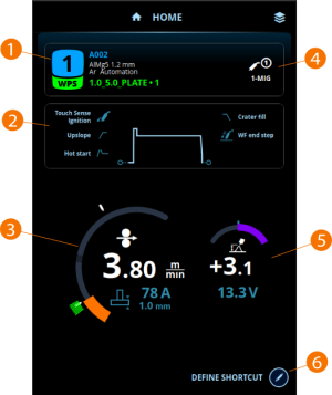
| 1. | Memory channel, welding program and WPS (if in use) |
| 2. | Applied welding parameters and functions |
| 3. | Wire feed speed |
>> With 1-MIG + WisePenetration and Pulse + WisePenetration combinations current is displayed
>> With MAX Position process plate thickness is displayed
>> The white marks indicate the adjustment range
>> The green mark indicates the adjustment range defined on the active WPS (If you adjust the welding parameters outside the adjustment range defined on the active WPS, a warning is displayed)
| 4. | Active welding process |
| 5. | Fine tuning |
>> With manual MIG process welding voltage is displayed
>> With Wise/MAX process a corresponding Wise/MAX parameter adjustment is displayed
| 6. | Configurable shortcut |
>> To define a shortcut, select the Edit button and then select the shortcut from the list of available options.
Home view during welding
During welding, the welding data is displayed in the welding data window.
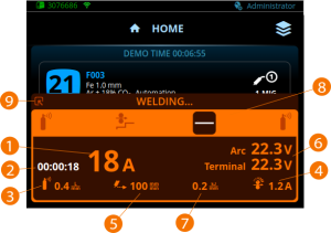
| 1. | Welding current |
| 2. | Welding duration |
| 3. | Shielding gas flow rate (in R500 Wire Feeder EUR+ models only when the gas flow sensor is activated in Robot settings) |
| 4. | Wire feeder motor current |
| 5. | Welding travel speed (if the robot provides the welding travel speed in the fieldbus control table) |
| 6. | Arc voltage and terminal voltage |
| 7. | Heat input calculation (if the robot provides the welding travel speed in the fieldbus control table) |
| 8. | Welding cycle with the ongoing phase highlighted. |
| 9. | Minimizes the welding data window to an icon. Selecting the icon restores the welding data window. |
The welding cycle symbols are explained in the following table:
| Symbol | Description |
|---|---|

|
Pre and post gas |

|
Creep start |

|
Upslope |

|
Hot start |

|
Continuous welding |

|
Crater fill |
Home view in online control mode
In online control mode the robot controls the values of certain welding parameters directly. For more information, refer to Online control.
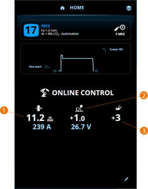
| 1. | Wire feed speed |
>> With 1-MIG + WisePenetration and Pulse + WisePenetration combinations current is displayed
>> With MAX Position process plate thickness is displayed
| 2. | Fine tuning |
>> With manual MIG process welding voltage is displayed
>> With Wise/MAX process a corresponding Wise/MAX parameter adjustment is displayed
| 3. | Dynamics |
>> Displayed only with 1-MIG, manual MIG, MAX Position and WiseThin+ processes.

|
After each weld, a weld summary (Weld data) is displayed briefly. |