Pre and post gas control
By default, AX MIG Welder uses the pre and post gas times set in the memory channels. However, the robot can override these values in order to use longer gas times than the maximum times available in AX Manager.
The following sections describe the different scenarios for pre and post gas control.
Scenario 1: Memory channel-controlled pre and post gas
In scenario 1, a memory channel controls both the pre and post gas times. This scenario requires either of the following settings:
| a. | the setting 'Pre and post gas control' is set to 'Memory channel' (refer to Robot settings) |
| b. | the setting 'Pre and post gas control' is set to 'Robot', but the 'GasBlow' control bit is not controlled by the robot during the welding cycle. |
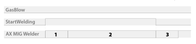
The sequence of phases in the welding cycle is as follows:
| 1. | The robot sets the 'StartWelding' control bit to state 1: the memory channel-controlled pre gas flow starts. |
| 2. | Once the memory channel-controlled pre gas time has elapsed, the arc ignites and welding starts. |
| 3. | The robot sets the 'StartWelding' control bit to state 0: welding ends and memory channel-controlled post gas flow starts. |
| 4. | Once the memory channel-controlled post gas time has elapsed, the gas valve closes and post gas flow ends. |
Figure 1: Memory channel-controlled pre and post gas
| Item | Description |
|---|---|
| 1 | Memory channel-controlled pre gas |
| 2 | Welding |
| 3 | Memory channel-controlled post gas |
Scenario 2: Robot-controlled pre and post gas
In scenario 2, the robot controls both the pre and post gas times. This scenario requires the following settings:
| • | the setting 'Pre and post gas control' is set to 'Robot' (refer to Robot settings) |
| • | the robot controls the 'GasBlow' control bit during the welding cycle. |
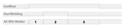
The sequence of phases in the welding cycle is as follows:
| 1. | The robot sets the 'GasBlow' control bit to state 1: the gas valve opens and robot-controlled pre gas flow starts. |
| 2. | Once the robot-controlled pre gas time has elapsed, the robot sets the 'StartWelding' control bit to state 1: the arc ignites and welding starts. |
| 3. | The robot sets the 'StartWelding' control bit to state 0: the arc is switched off, welding ends and robot-controlled post gas flow starts. |
| 4. | Once the robot-controlled post gas time has elapsed, the robot sets the 'GasBlow' control bit to state 0: the gas valve closes and post gas flow ends. |
Figure 2: Robot-controlled pre and post gas
| Item | Description |
|---|---|
| 1 | Robot-controlled pre gas |
| 2 | Welding |
| 3 | Robot-controlled post gas |
Scenario 3: Robot-controlled pre gas and memory channel-controlled post gas
In scenario 3, the robot controls the pre gas time and a memory channel controls the post gas time.
This scenario requires that the setting 'Pre and post gas control' is set to 'Robot' (refer to Robot settings).
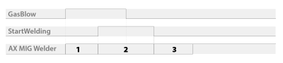
The sequence of phases in the welding cycle is as follows:
| 1. | The robot sets the 'GasBlow' control bit to state 1: the gas valve opens and robot-controlled pre gas flow starts. |
| 2. | Once the robot-controlled pre gas time has elapsed, the robot sets the 'StartWelding' control bit to state 1: the arc ignites and welding starts. |
| 3. | During welding, the robot sets the 'GasBlow' control bit to state 0 to enable memory channel-controlled post gas. |
| 4. | The robot sets the 'StartWelding' control bit to state 0: the arc is switched off, welding ends and memory channel-controlled post gas flow starts. |
| 5. | Once the memory channel-controlled post gas time has elapsed, the gas valve closes and post gas flow ends. |
Figure 3: Robot-controlled pre gas and memory channel-controlled post gas
| Item | Description |
|---|---|
| 1 | Robot-controlled pre gas |
| 2 | Welding |
| 3 | Memory channel-controlled post gas |
Scenario 4: Memory channel-controlled pre gas and robot-controlled post gas
In scenario 4, a memory channel controls the pre gas time and the robot controls the post gas time.
This scenario requires that the setting 'Pre and post gas control' is set to 'Robot' (refer to Robot settings).
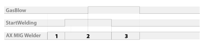
The sequence of phases in a welding cycle is as follows:
| 1. | The robot sets the 'StartWelding' control bit to state 1: the gas valve opens and memory channel-controlled pre gas flow starts. |
| 2. | Once the memory channel-controlled pre gas time has elapsed, the arc ignites and welding starts. |
| 3. | During welding, the robot sets the 'GasBlow' control bit to state 1 to enable robot-controlled post gas. |
| 4. | The robot sets the 'StartWelding' control bit to state 0: the arc is switched off, welding ends, and robot-controlled post gas flow starts and goes on as long as the 'GasBlow' control bit is in state 1. |
| 5. | Once the robot-controlled post gas time has elapsed, the robot sets the 'GasBlow' control bit to state 0: the gas valve closes and post gas flow stops. |
Figure 4: Memory channel-controlled pre gas and robot-controlled post gas
| Item | Description |
|---|---|
| 1 | Memory channel-controlled pre gas |
| 2 | Welding |
| 3 | Robot-controlled post gas |