Changing wire spool

|
Install the welding gun to the wire feeder before installing the wire spool. |

|
If you change the filler wire to a different diameter or material, change the feed rolls accordingly. |
Proceed as follows:
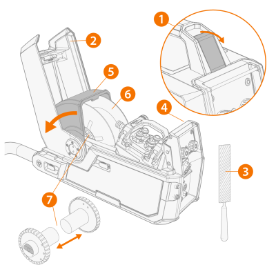
Remove the wire spool:
|
1.
|
Open the top cover latch. |
|
2.
|
Lift the top cover up. |
|
3.
|
Cut and file the tip of the filler wire. |
|
|
The sharp cut tip of the filler wire may cause damage to the wire liner, if not filed. |
|
4.
|
Press Wire retract to pull back the remaining filler wire from the welding gun. |

|
5.
|
Push the wire spool locking cover aside. |
|
6.
|
Lift the wire spool from the wire feeder. |
|
7.
|
Loosen and pull the wire spool brake halves apart. |
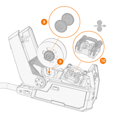
Install a new wire spool:
|
8.
|
Attach the wire spool brake halves to the new wire spool by pushing them together inside the wire spool. Tighten if necessary. |
|
|
The spool brake is equipped with an optional wire tensioning feature, which keeps the wire feed steady in short repeated welds and with heavy wire spools. To enable wire tensioning, attach the spool brake hub to the wire spool so that the tightening knob is on the right, seen from the front. |
|
9.
|
Lower the wire spool to its socket. |
|
|
Ensure that the wire spool is facing the right direction, the filler wire running from the top of the spool to the feed rolls. |
|
10.
|
Lift the pressure handle off of the feed rolls. |
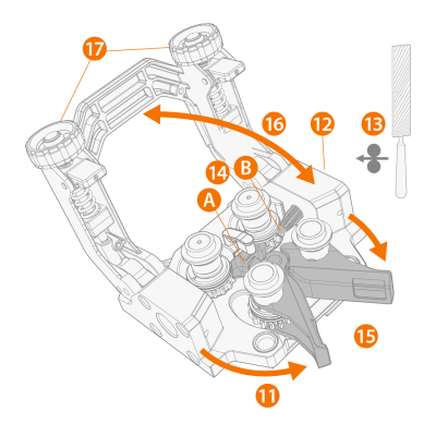
Install the filler wire:
|
11.
|
Release the pressure arms to move the feed rolls apart. This opens a gap between the feed rolls. |
|
12.
|
Release the filler wire end from the spool and cut off any deformed section so that the end is straight. |
|
|
Ensure that the filler wire does not spill from the spool when it is released. |
|
13.
|
File the tip of the filler wire smooth. |
|
|
Sharp edges on the filler wire tip may damage the wire liner. |
|
14.
|
Guide the filler wire through the inlet tube (A) and middle wire guide tube (B) to the outlet, which feeds the filler wire to the welding gun. Push the filler wire by hand inside the gun so that the wire reaches the wire liner (about 20 cm). |
|
15.
|
Close the pressure arms so that the filler wire is locked between the feed rolls. Ensure that the filler wire sits in the feed roll grooves. |
|
16.
|
Lower the pressure handle on the feed rolls. |
|
17.
|
Adjust the pressure of the feed rolls with the pressure adjustment wheels. The pressure is the same for both feed roll pairs. |
The graduated scales on the pressure handle indicate the pressure applied to the feed rolls. Adjust the pressure of the feed rolls according to the table below.
| Fe/Ss solid |
V-groove
 |
0.8−1.0 |
1.5−2.0 |
| ≥ 1.2 |
2.0−2.5 |
| Metal and flux cored |
V-groove, knurled
 |
≥ 1.2 |
1.0−2.0 |
| Self-shielded |
V-groove, knurled
|
≥ 1.6 |
2.0−3.0 |
| Aluminium |
U-groove
 |
1.0 |
0.5−1.0 |
| 1.2 |
1.0−1.5 |
| 1.4 |
1.5−2.0 |
| ≥ 1.6 |
2.0−2.5 |
|
|
Excessive pressure flattens the filler wire and may damage coated or cored filler wires. Excessive pressure also unnecessarily wears the feed rolls and increases gearbox load. |
|
18.
|
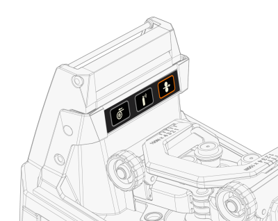
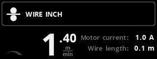
Press Wire inch to drive the filler wire to the welding gun's contact tip. To speed up the wire feed speed, turn the left control knob on the control panel. |
|
|
The control panel shows how much the filler wire has run. |
Finalize the installation:
|
19.
|
Select the shielding gas and attach the gas cylinder to the wire feeder. |
|
20.
|
Press Gas test to flush the former shielding gas from the system. |
|
|
You can also use this button to test that the gases flow through the system properly. |