Control Pad
This section describes the structure of Control Pad.
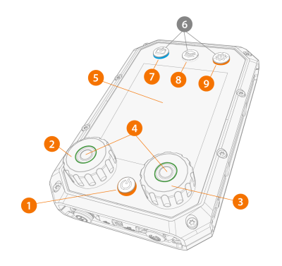
>> The button lights up orange, when you switch Control Pad on.
>> When the button lights up green, you can press the button to confirm an action.
>> The button lights up blue, when the view is activated.
>> The button lights up white, when the view is activated.
>> The button lights up orange, when the view is activated.
|
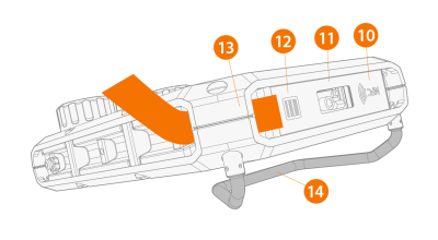
12.
|
ON/OFF button for NFC and barcode readers |
>> The button also acts as a shortcut button for reading a barcode in any Control Pad view.
|
13.
|
Loop for the carrying strap |
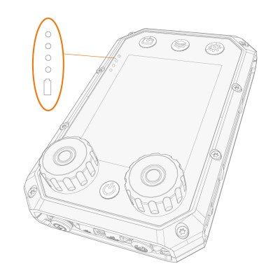
>> When you connect or disconnect the charger, Control Pad shows you the charge level.
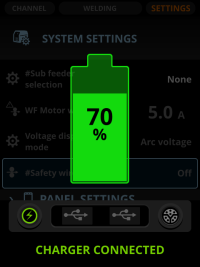
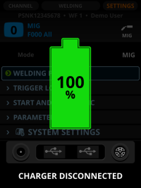
When Control Pad is charging, green leds on the left side of the display indicate ongoing charging. The lowest led turns red when the charge level is low.
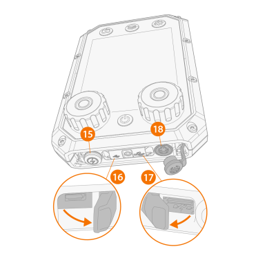
>> A stopper shields the charger cable port.
>> A cover shields the micro USB port and the USB cable port.
>> Combo cable port transfers both data and power. A stopper shields the combo cable port.