X5 Power Source 400 and 500
This section describes the structure of X5 Power Source 400 and X5 Power Source 500 models.
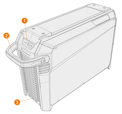
Front:
|
2.
|
Transportation handle (not intended for mechanical lifting) |
|
3.
|
Front locking interface (locking on top of the cooling unit or on the cart) |
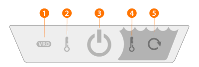
* Indicator panel
|
1.
|
VRD (Voltage Reduction Device) indicator |
>> The LED is green when VRD is switched on and the no-load voltage is under 35 V.
>> The LED blinks red when VRD is switched on and the no-load voltage is above 35 V.
>> The LED is off when VRD is switched off or during welding.
>> The LED blinks green when the MMA or Gouging power save mode is on (the power save mode is automatically applied after 15 minutes of idling).

|
VRD is in use with MMA and Gouging modes only. |
|
2.
|
High temperature indicator (overheating) |
>> The LED is yellow when the unit is overheating.

|
If the power source overheats, a thermal cutoff switches the unit off and does not allow it to be used until it has cooled down. |
|
3.
|
Power on/off indicator |
>> The LED is green when the unit is on.
|
4.
|
Coolant temperature warning |
>> The LED is yellow when the cooler is overheating.
|
|
If the coolant liquid overheats, a thermal cutoff switches the welding system off and does not allow it to be used until the coolant liquid has cooled down. |
|
5.
|
Coolant circulation warning |
>> The LED is green when the coolant circulation is working normally.
>> The LED is red when there is a problem in the coolant circulation.
|
|
If the circulation of the coolant liquid is obstructed, a thermal cutoff switches the welding system off. Check and fix the error before using the welding system again.
|
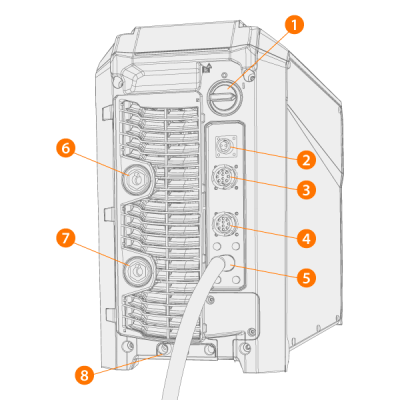
Rear:
|
2.
|
Voltage sensing cable connector (Pulse+ power sources only) |
|
3.
|
Control cable connector |
|
4.
|
Control cable connector |
|
6.
|
Welding current cable connector, plus (+) connector |
|
7.
|
Earth return cable connector, minus (-) connector |
|
8.
|
Rear locking interface |
>> For locking on top of the cooling unit or on the cart.