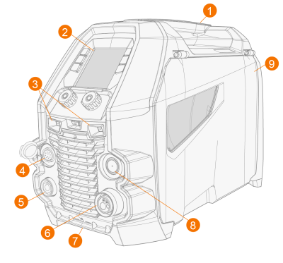
Master M device
Front
|
1.
|
Transportation handle (also for mechanical lifting when the device is not installed on a cooling unit or cart) |
|
3.
|
LED work lights with light switch in the middle |
>> Light switch: First press turns the lights on (full brightness), second press dims the lights (medium brightness), third press turns the lights off
>> Includes a built-in battery (the battery is charged when the equipment is connected to mains)
|
4.
|
Control cable connector |
|
5.
|
Earth return cable connector |
|
6.
|
Welding cable euro connector |
|
7.
|
Front locking interface |
>> For locking on top of the cooling unit or on the cart
|
8.
|
Subfeeder synchronization connector |
|
9.
|
Wire feed cabinet hatch. |
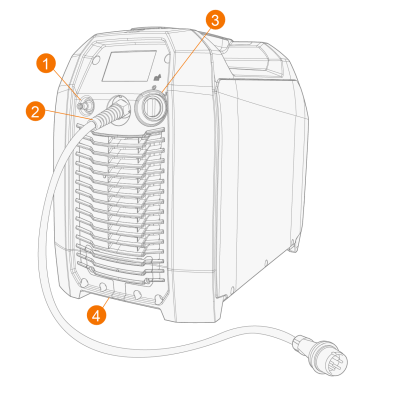
Rear
|
1.
|
Shielding gas hose connector |
|
4.
|
Rear locking interface |
>> For locking on top of the cooling unit or on the cart.
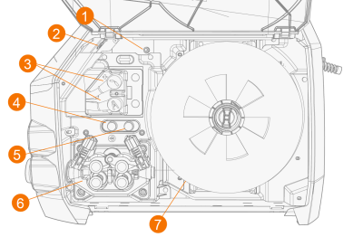
Inside wire feed cabinet
|
1.
|
Gas regulating valve (Master M 355) |
>> For setting the gas flow rate in the device lower than the gas flow rate from the gas supply
>> Drive the filler wire forward (with arc off)
>> Test the shielding gas flow and flush the gas line