Settings view
To adjust settings:
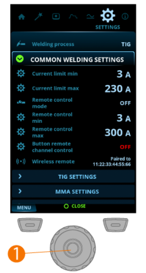
| 1. | Go to the Settings view. |
| 2. | Turn the control knob (1) to browse through the settings groups and parameters. |
| 3. | Select a parameter to be adjusted or changed by pressing the control knob button (1). |
| 4. | Adjust or change the setting by turning the control knob (1). |
| 5. | Close the parameter setting by pressing the control knob button (1). |

|
Some of the settings are e.g. current mode and welding process specific and are visible or not visible in the settings menu accordingly. |
Common welding settings:
| Parameter | Value | Note |
|---|---|---|
| Welding process | TIG / MMA / Cleaning / Polishing (Default = TIG) | Selecting a welding process changes automatically to the last active channel for the selected process. |
| Current limit min | TIG: 2 A / MMA: 8 A, step 1 A * | |
| Current limit max | TIG: power source's nominal value / MMA: power source's max. MMA current, step 1 A * | |
| Remote control mode | OFF / Remote / Torch (Default = OFF) | When a remote control or a torch remote control is selected, the welding current adjustment on the control panel is disabled. |
| Remote control min | Min = “Current limit min”, Max = “Current limit max” | |
| Remote control max | Min = “Current limit min”, Max = “Current limit max” | |
| Button remote channel control | OFF / ON (Default = OFF) | |
| Wireless remote | Pairing starts automatically when selected | New pairing information replaces the old information. Pairing status is shown as the settings value. |
TIG settings:
| Parameter | Value | Note |
|---|---|---|
| AC electrode type | Default / Green | AC electrode type. If you are using the green AC electrode type, select Green. Default applies to all other AC electrode types. |
| Balance limit min | -99 ... 0, step 1 (Default = -60) | |
| Balance limit max | 0 ... +20, step 1 (Default = 0) | |
| Lift TIG current | 5 A ... 40 A / Auto, step 1 A (Default = Auto = 10 A) | Contact current in the beginning of Lift TIG ignition. |
| HF spark force | 50 % ... 110 %, step 1 % (Default = 100 %) | Adjusts the voltage of the high frequency spark used in ignition. |
| DC Positive ignition current | 30 % ... 150 % / Auto, step 1 % (Default = Auto) | Adjusts the current level of the positive ignition sequence in DC current mode. Only in ACDC power sources. |
| DC Positive ignition time | 0 ms ... 200 ms / Auto, step 10 ms (Default = Auto) | Adjusts the length of the positive ignition sequence in DC current mode. Only in ACDC power sources. |
| DC Negative ignition current | 100 % ... 300 % / Auto, Step 1 % (Default = Auto) | Adjusts the current level of the negative ignition sequence in DC current mode. Only in ACDC power sources. |
| Ignition current | 100 % ... 300 % / Auto, step 1 % (Default = Auto) | Adjusts the current level of the negative ignition sequence. Only in DC power sources. |
| DC Negative ignition time | 0 ms ... 950 ms / Auto, step 10 ms (Default = Auto) | Adjusts the length of the positive ignition sequence in DC current mode. Only in ACDC power sources. |
| Ignition time | 0 ms ... 950 ms / Auto, step 10 ms (Default = Auto) | Adjusts the length of the negative ignition sequence. Only in DC power sources. |
| AC Positive ignition current | 30 % ... 150 % / Auto, step 1 % (Default = Auto) | Adjusts the current level of the positive ignition sequence in AC current mode. Only in ACDC power sources. |
| AC Positive ignition time | 0 ms ... 200 ms / Auto, step 10 ms (Default = Auto) | Adjusts the length of the positive ignition sequence in AC current mode. Only in ACDC power sources. |
| AC Negative ignition current | 100 % ... 300 % / Auto, Step 1 % (Default = Auto) | Adjusts the current level of the negative ignition sequence in AC current mode. Only in ACDC power sources. |
| AC Negative ignition time | 0 ms ... 950 ms / Auto, step 10 ms (Default = Auto) | Adjusts the length of the negative ignition sequence in AC current mode. Only in ACDC power sources. |
| Slight upslope | OFF / ON (Default = OFF) | This is a function that automatically creates a slight upslope to prevent electrode wearing caused by sudden current rises with high welding currents. This function has an effect only when the welding current is 100 A or more. |
| Startup level | 5 % ... 40 %, step 1 % (Default = 25 %) | The point of welding current where the upslope begins. |
| Downslope cut level | 5 % ... 40 %, step 1 % (Default = 10 %) | The point of welding current where the downslope ends. |
| 2T downslope cut | OFF / ON (Default = OFF) | This is a function that allows the user to end the current downslope ramp with a quick press of the torch switch. |
| Nonlinear downslope | 0 % ... 50 %, step 1 % (Default = 0 %) | Determines a point to which current goes down as fast as possible and then starts normal downslope. |
| Current freezing | OFF / ON (Default = OFF) | Welding current can be freezed to a certain level during downslope by pressing the trigger. |
| TIG antifreeze | OFF / ON (Default = OFF) | A function which automatically decreases the welding current significantly when electrode is touching the workpiece. Can be used for example to avoid unwanted dilution from electrode to welded metal. |
| AC phase swap current | 5 A ... 20 A / Auto | Changes the welding current point where crossing the zero begins. Affects only AC TIG. |
MMA settings:
| Parameter | Value | Note |
|---|---|---|
| Welding current | Min/Max = Normal welding current limits | |
| Hot start | -10 ... +10, step 1 (Default = 0) | Welding function that uses higher welding current at the start of the weld. After the Hot start period the current drops to normal welding current level. The values for Hot start current level and its duration are preset manually. This facilitates the start of the weld especially with aluminum materials. |
| Arc force | -10 ... +10, step 1 (Default = 0) | Adjusts short circuit dynamics (roughness) of MMA welding by changing, for example, current levels. |
| MMA antifreeze | OFF / ON (Default = OFF) | A function which automatically decreases the welding current significantly when electrode is touching the workpiece. Can be used for avoiding MMA electrode getting too hot when it’s in contact with the workpiece. |
| VRD mode | OFF / ON (Default = OFF) | This setting can be locked so that the user cannot change it. In the equipment models where the VRD mode is locked permanently to ON (e.g. AU model), the VRD option is still visible in the settings, but it cannot be changed. |
System settings:
| Parameter | Value | Note |
|---|---|---|
| Water cooler | OFF / Auto / ON (Default = Auto) | |
| Cooler flow watch | OFF / ON (Default = ON) | |
| Brightness | 10 % ... 100 %, step 1 % (Default = 100 %) | |
| Weld data time | 1 s ... 10 s, step 1 s (Default = 5 s) | |
| Show Weld Assist | ON / OFF (Default = ON) | A wizard-like utility for easy selection of welding parameters. The utility walks the user step-by-step through the selection of required parameters, presenting the selections in an easily understandable way for a non-technical user. |
| Screen saver | Default = Kemppi logo | An alternative screen saver image can be used. For more information, refer to Screen saver. |
| Screen saver time | OFF / 1 min ... 120 min, step 1 min (Default = 5 min) | |
| Date | Date setting (DD/MM/YYYY) | |
| Time (24h) | Time setting (HH:MM) | |
| Language | Language setting |
Special functions:
| Parameter | Value | Note |
|---|---|---|
| Gas test | Gas test time: 0 s ... 60 s, step 1 s (Default = 20 s) | Activating this starts the gas test with default time. Time can be changed by turning the control knob. Gas test can be stopped by pressing the control knob again. |
| Demagnetization | Cancel / Start (Default = Cancel) | This activates the demagnetization of the work piece. For more information, refer to Demagnetizing workpiece. |
| Factory reset... | Cancel / Start (Default = Cancel) | This activates the factory reset to restore factory settings on the device. Once the factory reset is complete, the power source must be restarted manually. |
* Current range adjustable by welder in TIG welding:
| • | 2 A ... 130 A, 1 A step (Master T 245, limited supply mode) |
| • | 2 A ... 245 A, 1 A step (Master T 245) |
| • | 2 A ... 355 A, 1 A step (Master T 355) |
| • | 2 A ... 405 A, 1 A step (Master T 405) |
| • | Default = Nominal value of the power source. |
* Current range adjustable by welder in MMA welding:
| • | 8 A ... 85 A, 1 A step (Master T 245, limited supply mode) |
| • | 8 A ... 185 A, 1 A step (Master T 245) |
| • | 8 A ... 255 A, 1 A step (Master T 355) |
| • | 8 A ... 355 A, 1 A step (Master T 405) |
| • | Default = MMA maximum current of the power source. |