Installing and changing wire (200 mm spool)
This section describes how to install and change a 200 mm spool. The spool hub for a 200 mm spool is factory installed on Master M 205 and 323 machines. For instructions on installing a 100 mm spool, refer to Installing and changing wire (100 mm spool).

|
Install the welding gun to the Master M device before installing the wire spool. |
|
|
When changing the wire spool, remove the remaining filler wire from the welding gun and wire feed mechanism before removing the wire spool. |
|
|
Always ensure that the feed rolls are suitable for the filler wire (diameter and material) in question. For more information, refer to Wire feeder consumables.
|
To remove the wire spool:
|
1.
|
Open the wire feed cabinet hatch. |
|
2.
|
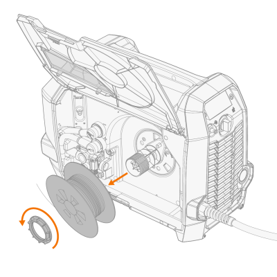
Loosen and remove the spool fastener and remove the wire spool. |
To install a new wire spool:
|
1.
|
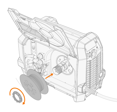
Insert the wire spool onto the spool hub. Secure the wire spool in place by inserting and tightening the spool fastener. |
|
|
Ensure that the wire spool is facing the right direction, the filler wire running from the bottom of the spool to the feed rolls. |
|
2.
|
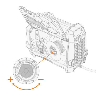
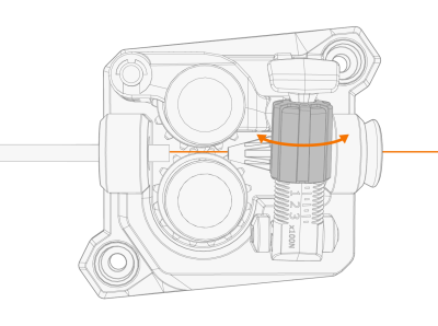
If needed, adjust the spool brake by turning the spool brake tightening knob in the center of the spool hub. |
To install the filler wire:
|
1.
|
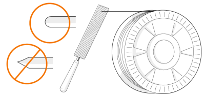
Release the filler wire end from the spool and cut off any deformed section so that the end is straight. |
|
|
Ensure that the filler wire does not spill from the spool when it is released. |
|
2.
|
File the tip of the filler wire smooth. |

|
Sharp edges on the filler wire tip may damage the wire liner. |
|
3.
|
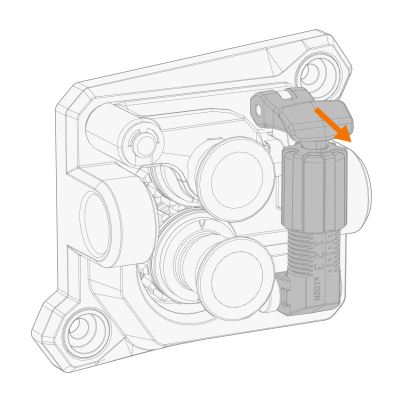
Release the pressure handle. |
|
4.
|
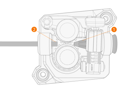
Guide the filler wire through the inlet guide tube (1) and into the outlet guide tube (2), which feeds the filler wire to the welding gun. |
|
5.
|
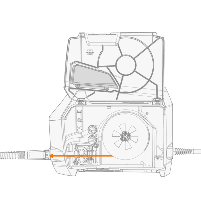
Push the filler wire by hand into the gun so that the wire reaches the wire liner. |
|
6.
|
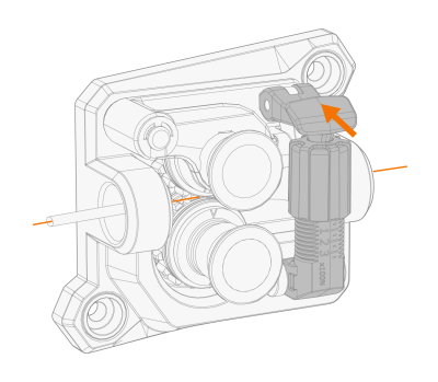
Close the pressure handle so that the filler wire is locked between the feed rolls. |
|
7.
|
Adjust the pressure of the feed roll with the pressure adjustment wheel. |
The graduated scales on the pressure arm indicate the pressure applied to the feed rolls. Adjust the pressure of the feed rolls according to the table below.
| Fe/Ss solid |
V-groove
|
0.8−1.0 |
1.5−2.0 |
| ≥ 1.2 |
2.0−2.5 |
| MC/FC |
V-groove, knurled
|
≥ 1.2 |
1.0−2.0 |
| Al |
U-groove
|
1.0 |
0.5−1.0 |
| 1.2 |
1.0−1.5 |
|
|
Excessive pressure flattens the filler wire and may damage coated or cored filler wires. Excessive pressure also unnecessarily wears the feed rolls and increases gearbox load. |
|
8.
|
Drive the filler wire into the welding gun by using the wire inch function in the system settings or by long pressing the left control knob button. Stop when the wire reaches the welding gun's contact tip. |

|
Watch out for the wire when it reaches the contact tip and exits the gun. |
Before welding, ensure that the welding parameters and settings conform to your welding setup.
* Feed roll profiles and corresponding symbols
| V-groove |

|
| V-groove, knurled |

|
| U-groove |

|