Analog IO add-on card
The analog IO add-on card provides two 0 … 10 V analog inputs and two 0 … 10 V analog outputs. The analog IO add-on card can be used when wire feed speed and welding voltage or fine tuning need to be controlled from a robot that does not have fieldbus connectivity.
The figure below displays an overview of an analog IO add-on card.
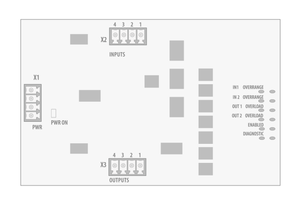
LED lights:
| LED | Description |
|---|---|
| PWR ON | Status of the external power supply of the analog IO add-on card. |
| IN1 OVERRANGE | Too high voltage on analog input 1. |
| IN2 OVERRANGE | Too high voltage on analog input 2. |
| OUT1 OVERLOAD | Too much load on analog output 1. |
| OUT2 OVERLOAD | Too much load on analog output 2. |
| ENABLED | Analog IO add-on card is active. |
| DIAGNOSTIC | Reserved for future use. |
Analog IO add-on card terminals:
| Terminal reference | Terminal name |
|---|---|
| X1 | Power supply input |
| X2 | Analog inputs |
| X3 | Digital outputs |
Power supply configuration
The analog IO add-on card requires an external 24 V power supply (not delivered with the AX MIG Welder equipment). The supply current for the analog IO add-on card is 0.1 A.
The pins of the power supply terminal X1 are as follows:

1. 24 V 2. GND 3. 24 V 4. GND |
Input configuration
The analog inputs are voltage measuring inputs with a measurement range of 0 … 10 V. The analog inputs are overvoltage protected up to a voltage of 24 V. If the voltage supplied to the analog input exceeds the measurement range, the corresponding “INx OVERRANGE” LED lights up.
The pins of the input connector X2 are as follows:
|
1. Analog input 1 2. GND 3. Analog input 2 4. GND |
Output configuration
The analog outputs are voltage sourcing outputs with a range of 0 … 10 V. The analog outputs are short-circuit protected. If the load connected to the analog output is too high, and the output voltage becomes distorted as a result, the corresponding “OUTx OVERLOAD” LED lights up.
The pins of the output connector X3 are as follows:
|
1. Analog output 1 2. GND 3. Analog output 2 4. GND |