Push-pull welding torch control cable connector
This section describes the order and purpose of the pins in the push-pull welding torch control cable connector used with third party push-pull welding torches.
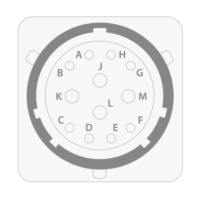
| Pin | Signal | Description |
|---|---|---|
| A | Encoder channel A input | Input for encoder channel A. |
| B | Encoder channel B input | Input for encoder channel B. |
| C | Hall sensor / encoder 5 V output | 5 V output for Hall sensors and encoder. |
| D | Hall sensor 1 input | Input for motor winding 1 Hall sensor. |
| E | Hall sensor 2 input | Input for motor winding 2 Hall sensor. |
| F | Hall sensor 3 input | Input for motor winding 3 Hall sensor. |
| G | Analog sync positive output | Differential analog voltage output for 3rd party push-pull welding torch control units. |
| H | Analog sync negative output | Differential analog voltage output for 3rd party push-pull welding torch control units. |
| J | Motor winding 1 | Output for motor winding 1. |
| K | Motor winding 2 | Output for motor winding 2. |
| L | Motor winding 3 | Output for motor winding 3. |
| M | Hall sensor / encoder GND | Ground for push-pull Hall sensors / encoder. |