Wire feeder peripheral connector
This section describes the order and purpose of the pins in the peripheral connector used for connecting welding torch auxiliary products.
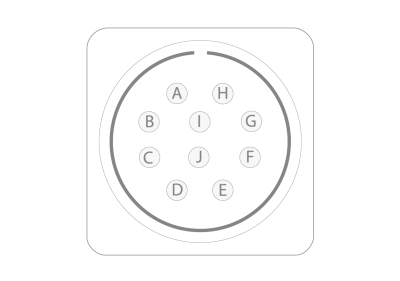
| Pin | Signal | Description |
|---|---|---|
| A | Motor (+) | For a push-pull welding torch |
| B | Motor (-) | For a push-pull welding torch |
| C | Supply (+24 V) | For a collision sensor with LED status indicators |
| D | Wire inch input | For a welding torch's wire inch button |
| E | Collision sensor input | For a collision sensor (ensure that your welding torch supports a collision sensor) |
| F | Touch sensor output (+50...+200 V) | For touch sensing with gas nozzle (ensure that your welding torch supports touch sensing with gas nozzle) |
| G | Tachometer (+5 V) | For a push-pull welding torch |
| H | Supply GND | - For a welding torch's wire inch button - For a collision sensor |
| I | Tachometer GND | For a push-pull welding torch |
| J | Tachometer input | For a push-pull welding torch |